
Sunday, April 23, 2017

Friday, May 17, 2013
R2-Q5 - Logic Displays
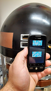
I'm thinking of using old cell phones to display the front and rear logic displays, set this to see how it would look. My thoughts were to run power through a usb cable and set it up to run an animated gif when turned on.



Thursday, April 18, 2013
R2-Q5 - Started painting the dome
Base coats are in bronze and the first coat of black applied. After the last coat of paint, I'll pull the tape to hopefully have some of the panels bronze matching the utility arms.


Sunday, March 24, 2013
R2-Q5 - Gets his dome trimmed


The sanding time saved on the trim was lost on the pie panels at the top. With R2-D2's panels having enough contrast between the blue panels and silver dome the fiberglass mold Todd Bixby uses doesn't need to have much definition. My imperial droid will be black panels on a black dome, so I needed to make the groves deeper. I tried everything from the Dremel cutting wheel, wood carving tools, and sand paper folded into corners, but this engraving bit for the Dremel seemed to work fast while keeping control.
The last piece for the night was to see if I could get the dome to spin on the frame. Using an 18" Rockler bearing from a local woodworking shop and an 18" floral wreath (particle board base) as a support ring in the dome. I drilled holes in the six bolt pattern on the support ring using the inner ring of the bearing as a template and connected them with 2" bolts and an extra set of nuts to adjust the space to help hide any imperfections in my cutting, mounting, or potential warping of the dome. I did leave it in my garage over the last summer and winter. Here's a video of me spinning it by hand.
Wednesday, July 11, 2012
Wifi garage door opener
I took apart my last garage door opener because there's another project that needs my bluetooth antenna. I realized how much easier the garage door opener would be to make over wifi and much less work to have it tidy in a permanent enclosure. Not to mention, the ethernet shield is roughly the same price as a 2nd antenna. This assumes you have wifi in your home with access from your driveway, a spare network port in your home network for the ethernet shield, and a cell phone.
![]() In the picture is the PCB from the inside of a traditional garage door opener is laid on top of the ethernet shield + arduino uno combo. The transistor is pushed into the heated solder points of the push button with the center pin going through a 10k resistor to the output pin of your choice.
In the picture is the PCB from the inside of a traditional garage door opener is laid on top of the ethernet shield + arduino uno combo. The transistor is pushed into the heated solder points of the push button with the center pin going through a 10k resistor to the output pin of your choice.
This 2nd example in this tutorial for lighting an LED can be copied without editing to use pin 2. The tutorial also walks you through testing the local address that will trigger the button. Now you can create a shortcut or bookmark to the website on your smartphone to be able to open with one click.
While this is all you need, I've also soldered wire to replace the battery. Since this one uses a 3v battery it's going to the 3.3v and ground pins on the board.
So in the rare occurance that I'd need to open the door while away (family member locked out of the house.. just takes one time). I decided to go with sending a text. For the time being I have an older android phone as a "home phone" and this script should be easy to replace the check for new texts section with anything from checking email to checking twitter and can easily grow into a smart home station. Aside from the wifi setup as the foundation, this involved downloading the SL4A app from here. Then create a Python script with the following code:
import android
import httplib
import time
droid = android.Android()
var = 1
while (var == 1):
smscheck = droid.smsGetMessages(True, 'inbox')
for i in smscheck.result:
if 'Open Sesame' in i['body']: # The command you want to send via text
url = '192.168.1.xxx' # IP address of ethernet shield goes here
uri = '/?2' # Pin number being used should replace 2
ES = httplib.HTTPConnection(url)
ES.request('GET',uri)
time.sleep(.5)
ESreply = ES.getresponse()
ES.close()
print ESreply
droid.smsDeleteMessage(i['_id'])
time.sleep(.25)
else:
time.sleep(.5)

This 2nd example in this tutorial for lighting an LED can be copied without editing to use pin 2. The tutorial also walks you through testing the local address that will trigger the button. Now you can create a shortcut or bookmark to the website on your smartphone to be able to open with one click.
While this is all you need, I've also soldered wire to replace the battery. Since this one uses a 3v battery it's going to the 3.3v and ground pins on the board.
Adding to it by opening with a text
So in the rare occurance that I'd need to open the door while away (family member locked out of the house.. just takes one time). I decided to go with sending a text. For the time being I have an older android phone as a "home phone" and this script should be easy to replace the check for new texts section with anything from checking email to checking twitter and can easily grow into a smart home station. Aside from the wifi setup as the foundation, this involved downloading the SL4A app from here. Then create a Python script with the following code:
import android
import httplib
import time
droid = android.Android()
var = 1
while (var == 1):
smscheck = droid.smsGetMessages(True, 'inbox')
for i in smscheck.result:
if 'Open Sesame' in i['body']: # The command you want to send via text
url = '192.168.1.xxx' # IP address of ethernet shield goes here
uri = '/?2' # Pin number being used should replace 2
ES = httplib.HTTPConnection(url)
ES.request('GET',uri)
time.sleep(.5)
ESreply = ES.getresponse()
ES.close()
print ESreply
droid.smsDeleteMessage(i['_id'])
time.sleep(.25)
else:
time.sleep(.5)
Thursday, July 5, 2012
R2-Q5 - Making a droid
 I've been a Star Wars fan since my parents took me to see Return of the Jedi when I was three years old. It's one of my earliest memories. Sitting in my dad's lap in a crowded theater and seeing luke wielding a green lightsaber with the sands of Tatooine in the background.
So when I started getting the bug to make stuff last summer, I came across astromech.net. A sight dedicated to droid builders of the R2 variety. A great site for collaborating ideas, tutorials, or just chatting on a regular basis with people who share the interest. With any large group there are a few bad apples, but I've found this to be a great community.
Here's a photo of how my droid has been sitting since the fall.
I'm going with R2-Q5 as the designation. There's something of a 10:1 ratio for R2-D2 vs. other full size replicas and imperial droids need to represent!
 This one will permanently be on all three feet. Apparently retracting feet are expensive to make, but it will be remote controlled with moving dome, opening doors, blinky lights, and sounds. The last piece I put together was a lens for the radar eye. The radar itself was made from Resin by Mansugi on astromech.net.
  The lens is from an arts and crafts ornament found at Michaels. An idea discussed at astromech.net. The diameter of the cut coincidentally matched my kitchen sink drain, which was used as a template. Yes, I went looking through the house like a Sesame Street episode looking for circles.
 The ornament ball is fairly sturdy, but I put too much pressure on it trying to rush through cutting. The edge of the dome is thicker than the top, meaning the breaking point isn't going to be on the piece of scrap. This is why I'm using a knife in the picture and taking my time.
 Here's the final fit before gluing in place.


Tuesday, April 3, 2012
Mad Genius Clock Design
I came up with what I believe to be a unique clock design a few months ago, but didn't have a name until today. The term mad genius was used by a friend today and I thought it fit. The clock only has an hour hand traveling back and forth through the spindle in a 12-point star pattern. I aim to have a physical model over the summer. Here is a rough animation of the pattern.


Tuesday, March 20, 2012
Temperature Triggered Light Switch
The idea for this project came to me 3-4 years ago late one cold winter night when I was called by my father-in-law. Some rural homes running on well water will have the water pump above ground and in a small building. Many of these pump houses, like the one at the house I rented from my father-in-law, can really ruin your day or week if a pipe bursts due to below freezing conditions. While I was appreciative of the call to save repair costs, fumbling around in a small building near mid-night looking for a lightswitch wasn't something I cared to do.
I could have hired someone, drawn an electrical line with a switch to the home, or created a wireless switch, but what if I hadn't gotten the call or what if I were out of town? I've always wanted a smart home and this was a start to doing it cheaply.

This first photo is a prototype board with an ATmega328 flashed with Arduino. A transformer to get power from AC is just below the picture in the box. The relay is triggered on pin 8 when the temp sensor reads 0 degrees C or below. The standard light switch can be used as a bypass and is mounted to the box cover. The LM75, temp sensor shown in the second photo, was scavenges from a 2004 iMac being sent to the recycler at work. The sensor is on a nice breakout board with connector. I've soldered these wires to an RJ11 socket at both the base unit and for the sensor. This will allow the sensor to be connected by a standard telephone wire. Between power and the I2C protocol all four wires of the telephone line are being used and cheaper wire with only two wires can't be used. To help keep the sensor weather resistent I used a clear christmas tree ornament from Michaels and sealed it with super glue. It survived 30 seconds under a running faucette so I'm gong to attempt to hang it under the roof's over hang.

The total cost of the project was under $15 with most of the compnents repurposed from tossed electronics. I hope to follow up with a photo of the box and switch installed in the pump house; conveniently after we've moved out of the rental house and just after another winter season. Of course, it's always the first frost that's hardest to remember!
I could have hired someone, drawn an electrical line with a switch to the home, or created a wireless switch, but what if I hadn't gotten the call or what if I were out of town? I've always wanted a smart home and this was a start to doing it cheaply.

This first photo is a prototype board with an ATmega328 flashed with Arduino. A transformer to get power from AC is just below the picture in the box. The relay is triggered on pin 8 when the temp sensor reads 0 degrees C or below. The standard light switch can be used as a bypass and is mounted to the box cover. The LM75, temp sensor shown in the second photo, was scavenges from a 2004 iMac being sent to the recycler at work. The sensor is on a nice breakout board with connector. I've soldered these wires to an RJ11 socket at both the base unit and for the sensor. This will allow the sensor to be connected by a standard telephone wire. Between power and the I2C protocol all four wires of the telephone line are being used and cheaper wire with only two wires can't be used. To help keep the sensor weather resistent I used a clear christmas tree ornament from Michaels and sealed it with super glue. It survived 30 seconds under a running faucette so I'm gong to attempt to hang it under the roof's over hang.

The total cost of the project was under $15 with most of the compnents repurposed from tossed electronics. I hope to follow up with a photo of the box and switch installed in the pump house; conveniently after we've moved out of the rental house and just after another winter season. Of course, it's always the first frost that's hardest to remember!
Thursday, August 4, 2011
Open garage door via cell phone bluetooth connection.
Pseudo Purpose:
I can't remember where I read about the idea, but it was while searching the web for stuff to do. The over all idea I went for was to connect my cell phone with a bluetooth device that will trigger my garage door to open or close on command. I chose bluetooth instead of through the web or wifi as I didn't want to accidentally leave my garage door open all day and if it were to be hacked it would have to be done a decent range of my house and not from someone half way around the globe. Why not just use the garage door opener? Well I have more than one car and just one remote and rarely do I not have my cell phone on me. Opening the garage door with my cell phone is easier than reaching into my daily driver and remembering to put the remote back before heading to work the next day. You can see it work on my YouTube video.
Parts:
Arduino Uno - Any micro controller will do, I started with arduino and the code below is purposefully for the Uno board, since that's what I had from other projects.
BlueSMiRF - The bluetooth antenna of my choosing. Namely because it was the cheaper of available options at around $40. I'll probably go with the gold instead of silver version in the future to get more range out of the wireless connection. An Xbee or Bluetooth Mate antenna would work as well.
2N2222 Transistor - Simply, there are 3 leads on this part and when electricity is sent down the middle lead it will bridge an electrical connection through the two outside leads.
Garage Door Remote - This can be the wall mounted internal remote or the remote for your car. I chose my car remote as it seemed easier to open the case.
Amarino app on Android phone - The Amarino app is designed to manage multiple bluetooth devices from your phone that can accept serial commands. It also has a library for simplifying the Arduino code needed to receive and respond to your cell phone. Amarino install instructions were fairly clear for me from their website.
Code:
I'm going to skip a bit of Arduino basics since it's covered so well on there website. Specifically with how to install their software, edit code, add a software library, and upload the code to your Arduino Uno. From the Amarino website. you'll need to follow the instructions for downloading and adding the MeetAndroid library found here. Once the library is added you should be able to copy the following code and upload it without editing.
#include <MeetAndroid.h>
MeetAndroid meetAndroid; // Declare MeetAndroid so that you can call
// functions with android devices over bluetooth.
int GaragePin = 9; // We need a pin to initiate the garage door
void setup()
{
Serial.begin(57600); // Use the baud rate your bluetooth module is configured to use.
meetAndroid.registerFunction(Garage, 'A'); // Register callback functions,
// which will be called when an associated event occurs.
// These match the "FLAG" used from Amarino
pinMode(GaragePin, OUTPUT); // set garage pin as output
}
void loop()
{
meetAndroid.receive(); // you need to keep this in your loop() to receive events
}
void Garage(byte flag, byte numOfValues) // Defining the function we registered above.
{
if (meetAndroid.getInt() == 999) { // replace 999 with any 1 to 5 digit code to keep
// the bluetooth door opener some what secure. This will be the number you type on your
// phone from the Amarino app to open/close the door.
analogWrite(GaragePin, 153); // Probably overly cautious, but on a scale of 0 to 255 with
// 0 volts being 0 volts and 255 being 5 volts I set the analog pin to 153 to
// roughly simulate 3 volts since that the battery in my garage door remote is a 3V battery and
// I didn't know or wanted to find out that 5v was too much for the circuit.
delay(0750); // simulate pushing the tactical button for 3/4 of a sec.
analogWrite(GaragePin, 0); // simulate releasing the button
}
}
Assembly:
First I setup and ran a test with the bluetooth connection using one of the MeetAndroid examples that came with the library. In fact the code above is a modified version of the multicolor led example.
I followed this tutorial for the test. Take Note: There is an RTS and CTS pin on the antenna that need to be wired together and I didn't see this mentioned on the link, which can provide hours of stress and self-doubt when you follow the tutorial step by step and it doesn't work. Once complete leave the wring in place and begin to hack into the garage door remote.
Usually there is a small indentation or gap not easily visible around the seam of the case. You should be able to slowly and firmly twist a flat head screw driver without breaking the case. If you want a visual reference search for how to change the battery in your specific brand of garage door remote. Now that it's open, identify which side of the button is positive and negative. There's 4 leads only 2 will be connected by either a trace in the PCB board linked to it or a resistor soldered directly to a lead. I jammed two jumper wires under the active leads on the button and connected the button's positive lead to the collector pin on the transistor and the button's negative lead to the transistor's emitter pin. The transistor's base pin is linked through a 10k resistor to pin 9 on the arduino board. Depending to the transistor you're using you'll need to look up the datasheet of that model to know the pin place and which size resistor to use on the base pin.
And that should do it.
Alternatives:
1. It may have been faster to test that the transistor was working by having it light an led when active then just connect it to the push button and reverse the leads if it didn't work. May have saved time and eye strain from tracing the PCB lines to find positive and negative leads on the button.
2. Research Arduino code for detecting if the bluetooth antenna has a successful connection. If I can change the standard authentication so not just anyone could connect than I could have Arduino just check for an active connection. When found open the door and drop the connection. This would mean no app needed for the phone, just an attempt to connect to the device will open or close the door.
3. I have a Parallax ultrasonic range sensor. Might be neat to have the door close automatically when the vehicle reached 6 inches from the back wall or use the sensor to close the door if the garage is left open for more than 10 min.
4. Swap bluetooth for http for connection to arduino, because your spouse or child calls you locked out of the house.
I can't remember where I read about the idea, but it was while searching the web for stuff to do. The over all idea I went for was to connect my cell phone with a bluetooth device that will trigger my garage door to open or close on command. I chose bluetooth instead of through the web or wifi as I didn't want to accidentally leave my garage door open all day and if it were to be hacked it would have to be done a decent range of my house and not from someone half way around the globe. Why not just use the garage door opener? Well I have more than one car and just one remote and rarely do I not have my cell phone on me. Opening the garage door with my cell phone is easier than reaching into my daily driver and remembering to put the remote back before heading to work the next day. You can see it work on my YouTube video.
Parts:
Arduino Uno - Any micro controller will do, I started with arduino and the code below is purposefully for the Uno board, since that's what I had from other projects.
BlueSMiRF - The bluetooth antenna of my choosing. Namely because it was the cheaper of available options at around $40. I'll probably go with the gold instead of silver version in the future to get more range out of the wireless connection. An Xbee or Bluetooth Mate antenna would work as well.
2N2222 Transistor - Simply, there are 3 leads on this part and when electricity is sent down the middle lead it will bridge an electrical connection through the two outside leads.
Garage Door Remote - This can be the wall mounted internal remote or the remote for your car. I chose my car remote as it seemed easier to open the case.
Amarino app on Android phone - The Amarino app is designed to manage multiple bluetooth devices from your phone that can accept serial commands. It also has a library for simplifying the Arduino code needed to receive and respond to your cell phone. Amarino install instructions were fairly clear for me from their website.
Code:
I'm going to skip a bit of Arduino basics since it's covered so well on there website. Specifically with how to install their software, edit code, add a software library, and upload the code to your Arduino Uno. From the Amarino website. you'll need to follow the instructions for downloading and adding the MeetAndroid library found here. Once the library is added you should be able to copy the following code and upload it without editing.
#include <MeetAndroid.h>
MeetAndroid meetAndroid; // Declare MeetAndroid so that you can call
// functions with android devices over bluetooth.
int GaragePin = 9; // We need a pin to initiate the garage door
void setup()
{
Serial.begin(57600); // Use the baud rate your bluetooth module is configured to use.
meetAndroid.registerFunction(Garage, 'A'); // Register callback functions,
// which will be called when an associated event occurs.
// These match the "FLAG" used from Amarino
pinMode(GaragePin, OUTPUT); // set garage pin as output
}
void loop()
{
meetAndroid.receive(); // you need to keep this in your loop() to receive events
}
void Garage(byte flag, byte numOfValues) // Defining the function we registered above.
{
if (meetAndroid.getInt() == 999) { // replace 999 with any 1 to 5 digit code to keep
// the bluetooth door opener some what secure. This will be the number you type on your
// phone from the Amarino app to open/close the door.
analogWrite(GaragePin, 153); // Probably overly cautious, but on a scale of 0 to 255 with
// 0 volts being 0 volts and 255 being 5 volts I set the analog pin to 153 to
// roughly simulate 3 volts since that the battery in my garage door remote is a 3V battery and
// I didn't know or wanted to find out that 5v was too much for the circuit.
delay(0750); // simulate pushing the tactical button for 3/4 of a sec.
analogWrite(GaragePin, 0); // simulate releasing the button
}
}
Assembly:
First I setup and ran a test with the bluetooth connection using one of the MeetAndroid examples that came with the library. In fact the code above is a modified version of the multicolor led example.
I followed this tutorial for the test. Take Note: There is an RTS and CTS pin on the antenna that need to be wired together and I didn't see this mentioned on the link, which can provide hours of stress and self-doubt when you follow the tutorial step by step and it doesn't work. Once complete leave the wring in place and begin to hack into the garage door remote.
Usually there is a small indentation or gap not easily visible around the seam of the case. You should be able to slowly and firmly twist a flat head screw driver without breaking the case. If you want a visual reference search for how to change the battery in your specific brand of garage door remote. Now that it's open, identify which side of the button is positive and negative. There's 4 leads only 2 will be connected by either a trace in the PCB board linked to it or a resistor soldered directly to a lead. I jammed two jumper wires under the active leads on the button and connected the button's positive lead to the collector pin on the transistor and the button's negative lead to the transistor's emitter pin. The transistor's base pin is linked through a 10k resistor to pin 9 on the arduino board. Depending to the transistor you're using you'll need to look up the datasheet of that model to know the pin place and which size resistor to use on the base pin.
And that should do it.
Alternatives:
1. It may have been faster to test that the transistor was working by having it light an led when active then just connect it to the push button and reverse the leads if it didn't work. May have saved time and eye strain from tracing the PCB lines to find positive and negative leads on the button.
2. Research Arduino code for detecting if the bluetooth antenna has a successful connection. If I can change the standard authentication so not just anyone could connect than I could have Arduino just check for an active connection. When found open the door and drop the connection. This would mean no app needed for the phone, just an attempt to connect to the device will open or close the door.
3. I have a Parallax ultrasonic range sensor. Might be neat to have the door close automatically when the vehicle reached 6 inches from the back wall or use the sensor to close the door if the garage is left open for more than 10 min.
4. Swap bluetooth for http for connection to arduino, because your spouse or child calls you locked out of the house.
Subscribe to:
Posts (Atom)